Elevation Drawings in Architecture: Exterior and Interior
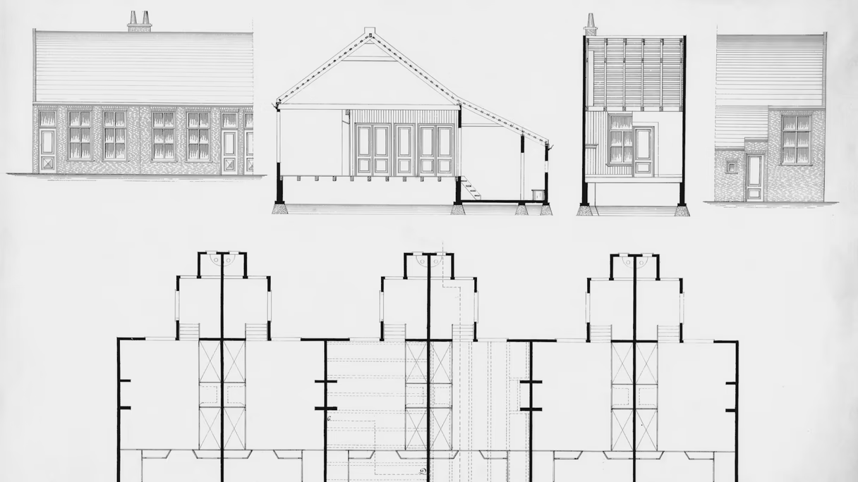
An elevation drawing is an orthographic view of one vertical surface of a building, drawn straight on, with no perspective. The surface is either an exterior facade or a wall inside a room. An elevation shows heights, openings and finishes that a floor plan cannot show. This guide explains what elevations are, how exterior and interior elevations differ, how they are named, how they compare with plans and sections, and how the elevations of an existing building are drawn from a laser scan.
What is an elevation view
An elevation is a representation of a vertical surface of a building, either a facade of the exterior or a wall in the interior, in the wording of a City Tech (CUNY) architecture course. It is drawn in orthographic projection: every line of the surface is projected at a right angle onto the sheet, so parallel edges stay parallel and nothing recedes toward a vanishing point. A window 4 feet wide measures 4 feet wide anywhere on the drawing, at the drawing’s scale.
That is the difference between an elevation and a photograph or a rendering. A photograph of a facade shows the near edge larger than the far edge and the upper floors leaning away. An elevation shows the facade as if the viewer stood at an infinite distance and looked at it square on, which makes it possible to take dimensions from it.
The terms “elevation view,” “building elevation,” “architectural elevation” and “elevation drawing” name the same thing. In a few contexts “elevation” also means a height above sea level or above a datum, such as the elevation of a floor slab. That is a number on the drawing, not the drawing itself.
Exterior elevations
An exterior elevation shows the outside of the building from one side. A full set normally has one elevation for each face of the building, so a rectangular building has four. The drawing shows:
- Overall height of the building and the height of the roof line, parapet and any rooftop element seen from that side.
- Floor levels, drawn as level lines at each floor’s finished elevation, usually with a dimension string along one side.
- Openings: the position, size and type of every window, door, louver and overhead door, with sill and head heights.
- Materials: brick, siding, stucco, metal panel or glazing, noted with labels or hatching.
- Grade: the ground line against the building, so the reader can see how much of the wall is above and below grade.
- Projections: balconies, canopies, bays, cornices, chimneys and stair towers, drawn with line weights that show which parts stand forward.
Interior elevations
An interior elevation shows one wall of a room as if the wall were laid flat in front of the viewer. A kitchen typically has four, one for each wall. The drawing shows the items fixed to or built against the wall:
- Base and wall cabinets, countertops, shelving and other casework or millwork
- Wall finishes, tile limits, wainscot heights and trim
- Doors, windows and openings in that wall, with their heights
- Wall-mounted items such as grab bars, mirrors, sinks, fixtures and equipment, with mounting heights
Interior elevations are drawn at a larger scale than exterior ones because the information is denser. They are referenced from the floor plan with a marker that says which wall, and which sheet carries the drawing.
How elevations are named
Exterior elevations are named by the side of the building they show. Two conventions are common: by compass direction (north, south, east and west elevation) or by the building’s own faces (front, rear, left and right, or the street elevation and the alley elevation). The name is the direction the face looks: the north elevation shows the face that looks north, as seen by a viewer standing north of the building. Compass names let each elevation be found against the north arrow on the site plan; on a building turned at an angle to north, a set may use the nearest direction or front, rear and side names, and the sheet index says which.
The HABS guidelines of the National Park Service set the order for a documentation set: “The sequence of elevations should begin with the front (entrance) elevation, and then move systematically either clockwise or counter-clockwise around the building.” Interior elevations are named by room and wall, or by the marker number on the plan.
On a drawing set organized to the U.S. National CAD Standard, elevations sit in the 200 series of sheets. A sheet identifier combines a discipline letter, a sheet-type digit and a sequence number, so A-201 is the first architectural elevation sheet. Enlarged interior elevations often go with the large-scale views of sheet type 4, which the UDS describes as scaled up plans, elevations or sections that are not details. A project can use its own numbering, and the cover sheet’s index is the authority.
Elevation vs section vs plan
The three drawings are cut or projected from the same building, and when drawn correctly they correspond to each other. A window that appears in an elevation appears as a horizontal cut in the exterior wall on the plan and as a vertical cut on the section.
| Plan | Elevation | Section | |
|---|---|---|---|
| View direction | Looking down | Looking straight at a vertical surface | Looking at a vertical cut through the building |
| Is the building cut | Yes, horizontally, typically 3 to 4 feet above the floor | No, it is a view of the surface | Yes, vertically |
| Shows well | Layout, wall positions, room sizes, door swings | Heights, openings, materials, roof line, grade | Floor to floor heights, ceiling heights, stairs, structure, wall build-up |
| Shows poorly | Vertical relationships between levels, finishes on the wall face | Anything behind the surface | What lies in front of the cut |
| Typical question | Where does the wall go? | What does the facade look like and how tall is it? | How is the building put together vertically? |
The cut height of a plan is the figure given in the CUNY lesson: a horizontal cut typically about three to four feet above the floor. The HABS guidelines add a rule that matters when elevations and plans are compared: plans and elevations are always drawn at the same scale, so that one can be laid over the other.
How elevations of an existing building are drawn from a laser scan
Before scanning, the elevations of an existing building were measured by hand. The HABS guidelines describe the method: elevations are measured with continuous vertical dimension strings, typically taken at every corner and through door and window openings, all referenced to a horizontal datum. For a building that is out of plumb, the surveyor hangs a plumb bob to capture the lean. HABS measures plans, elevations and sections to the nearest 1/8 inch. The guidelines also allow a laser total station to locate significant points on the building.
A 3D laser scan replaces the strings with a registered point cloud of the whole facade. The elevation is then traced from that cloud:
- The facade is scanned from the ground and from adjacent floors or roofs; upper floors that cannot be seen from there need a lift or aerial capture. Each scan is registered into one point cloud.
- A view is set square to the face of the building. The cloud is clipped to a depth range that removes the trees and cars in front of it, and projecting or recessed elements are traced at their own depth.
- The outline, floor lines, roof line and parapet are traced. Every window, door and louver is measured and drawn at its real position, so an opening that was widened or filled in decades ago appears as it stands.
- Materials are noted, with coursing drawn from the cloud where it matters. The HABS guidelines ask for brick joints drawn across the whole elevation and a vignette of measured vertical joints, not a generic hatch pattern, because standard hatch patterns do not represent actual conditions.
- The elevation is checked against the plans traced from the same cloud, so the openings agree in both.
A scanner of the Trimble X7 class holds a 3D point accuracy of 2.4 mm at 10 m and 3.5 mm at 20 m (one standard deviation) by its datasheet. That figure is one standard deviation, while a USIBD Level of Accuracy is stated at the 95 percent confidence level, so the two numbers are not compared directly. The accuracy of the drawing is stated separately, as a USIBD Level of Accuracy, because the line work is a representation of the cloud, not the cloud itself. A wall that leans is drawn as a line at the position the scan shows, and the drawing notes the lean where it matters.
The same scan produces the plans, sections and reflected ceiling plans, so the elevations agree with them without a second visit. We deliver elevations in DWG and PDF as part of a set of as-built drawings, traced from the registered point cloud. For a facade whose glazing is to be replaced, the elevation is one part of a larger record, which the guide to facade scanning for glazing and curtain wall replacement covers.
What elevations are used for
- Facade restoration and repair. The elevation records the pattern of masonry, the position of every opening and the extent of each projection, so that repair areas can be marked and quantities taken off.
- Storefronts and glazing. Opening sizes and head and sill heights set the dimensions of new frames. A scan finds the openings that are out of square before the new frames are ordered.
- Permits and design review. Many jurisdictions ask for elevations of the existing and proposed building, and historic review boards ask for them to judge the effect of a change on the street face.
- Renovation and additions. A new addition is drawn against the existing elevation, with the roof line, floor levels and window heads carried across.
- Historic documentation. A measured elevation is a core part of a record of a historic building, as the HABS guidelines show. The guide to 3D scanning for historic preservation describes how scanning fits that work.
Where plans are needed alongside the elevations, existing conditions documentation for renovation describes what a complete set holds.
FAQ
What is an elevation drawing in architecture?
An elevation drawing is a flat, straight-on view of one vertical surface of a building, either an exterior facade or an interior wall. It has no perspective, so heights and widths can be read to scale.
What is the difference between an exterior and an interior elevation?
An exterior elevation shows one face of the outside of the building: its height, floor levels, openings, materials, roof line and grade. An interior elevation shows one wall of a room, with casework, millwork, finishes and wall-mounted items.
What is the difference between an elevation and a section?
An elevation is a view of a surface and does not cut the building. A section is a vertical cut through the building that shows what is inside it, such as floor to floor heights, stairs and structure.
How many elevations does a building have?
A rectangular building usually has four exterior elevations, one for each face. A building with an irregular outline has more, and each room with elevations called out in the plan adds interior elevations.
How are elevations drawn from an existing building?
Traditionally by hand measurement with vertical dimension strings and a horizontal datum. Today the elevation is usually traced from a registered 3D laser scan of the facade, with every opening measured from the point cloud.
Why are elevations named north, south, east and west?
The compass name says which direction the face looks, so each elevation can be found against the north arrow on the site plan. Front, rear and side names are also used, particularly on small buildings with an obvious entrance side.
Sources
- National Park Service, HABS Guidelines for Measured Drawings (2008): measuring elevations with vertical strings and a datum, 1/8 inch measurement, brick joint drawing, same scale for plans and elevations, sequence of elevations (sections 3.4, 4.6, 5.2 and 5.3).
- City Tech (CUNY) OpenLab, Lesson 3: Introduction to Architectural Drawings, Elevations: definition of an elevation, and how plan, section and elevation correspond.
- National CAD Standard, Uniform Drawing System Module 1: Drawing Set Organization: sheet identifiers and sheet type 2 for elevations.
- Trimble X7 3D laser scanning system datasheet: 3D point accuracy of 2.4 mm at 10 m and 3.5 mm at 20 m.
- USIBD, Level of Accuracy: the Level of Accuracy framework for stating drawing accuracy.