Architectural Drawings: Types, Sheet Numbers and Scales
Architectural drawings are the scaled drawings that describe a building: its layout, its outside faces, its internal heights and the construction of its parts. They are produced by an architect or a drafter and are used to design the building, to get it permitted, to price it and to build it. This guide explains the main types of architectural drawings, how a US drawing set is numbered, how design drawings differ from construction documents and as-builts, and how drawings of an existing building are made from a laser scan.
What are architectural drawings
Architectural drawings are scaled, orthographic drawings (plans, elevations, sections, details and schedules) that describe a building so it can be designed, permitted, priced and built. Most are orthographic: each one looks at the building along a single direction, so there is no perspective and dimensions can be read to scale. A plan looks down, an elevation looks straight at a vertical surface, and a section looks at a vertical cut. The City Tech (CUNY) architecture course defines the three this way: a plan is a horizontal slice through the building, a section is a vertical slice, and an elevation is a representation of a vertical surface of a building, such as an exterior facade or an interior wall.
No single drawing describes a building. A set of architectural drawings covers the whole building through many views, and each view answers a different question: where the walls are, how tall the rooms are, what the facade looks like, how the roof meets the wall. The sheets refer to each other with markers and sheet numbers.
Types of architectural drawings
The list below follows the order in which a set is usually read, from the site down to the detail. For the types where we have a full guide, the link goes to it.
Site plan. A site plan shows the building in relation to its lot: the building outline or roof, and the features around it. It is drawn at a smaller scale than the building plans. The National Park Service’s HABS drawing guidelines say site plans are typically drawn at an engineering scale such as 1”=20’-0”, 1”=30’-0” or 1”=40’-0”.
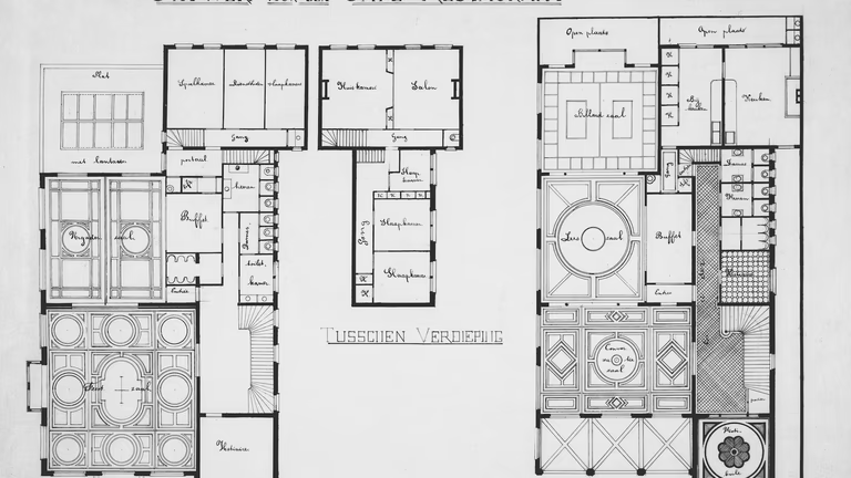
Floor plan. A floor plan is a horizontal cut through the building, seen from above. It shows walls, openings, stairs, room names and dimensions. The cut is usually taken about 3 to 4 feet above the floor, so it passes through windows and door openings and shows them in the wall. There is one plan per floor, usually on its own sheet in a multi-story building.
Reflected ceiling plan. A reflected ceiling plan shows the ceiling as if mirrored on the floor, in the same orientation as the floor plan, so the two sheets line up. It carries ceiling heights, the grid, soffits, lights, air diffusers and sprinkler heads.
Roof plan. A roof plan is the roof seen from directly above. It shows the roof outline, slopes, drainage, penetrations and rooftop equipment. In most sets it is its own sheet in the plan series.
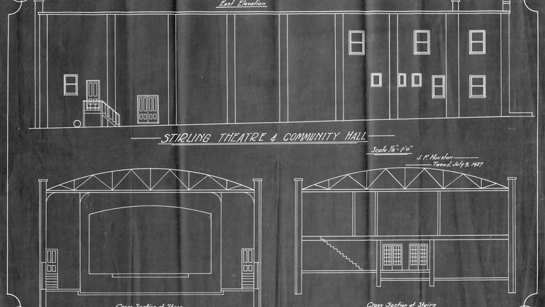
Elevations. An elevation drawing is a flat, straight-on view of one vertical surface. Exterior elevations show each face of the building, with openings, materials and heights. Interior elevations show the walls of a room, such as a kitchen or a lobby, at a larger scale.
Sections. A section drawing is a vertical cut through the building, viewed in one direction. It shows floor and ceiling heights, structure, stairs and how the levels relate. Building sections cut the whole building, wall sections cut one wall from foundation to roof, and detail sections cut a small part.
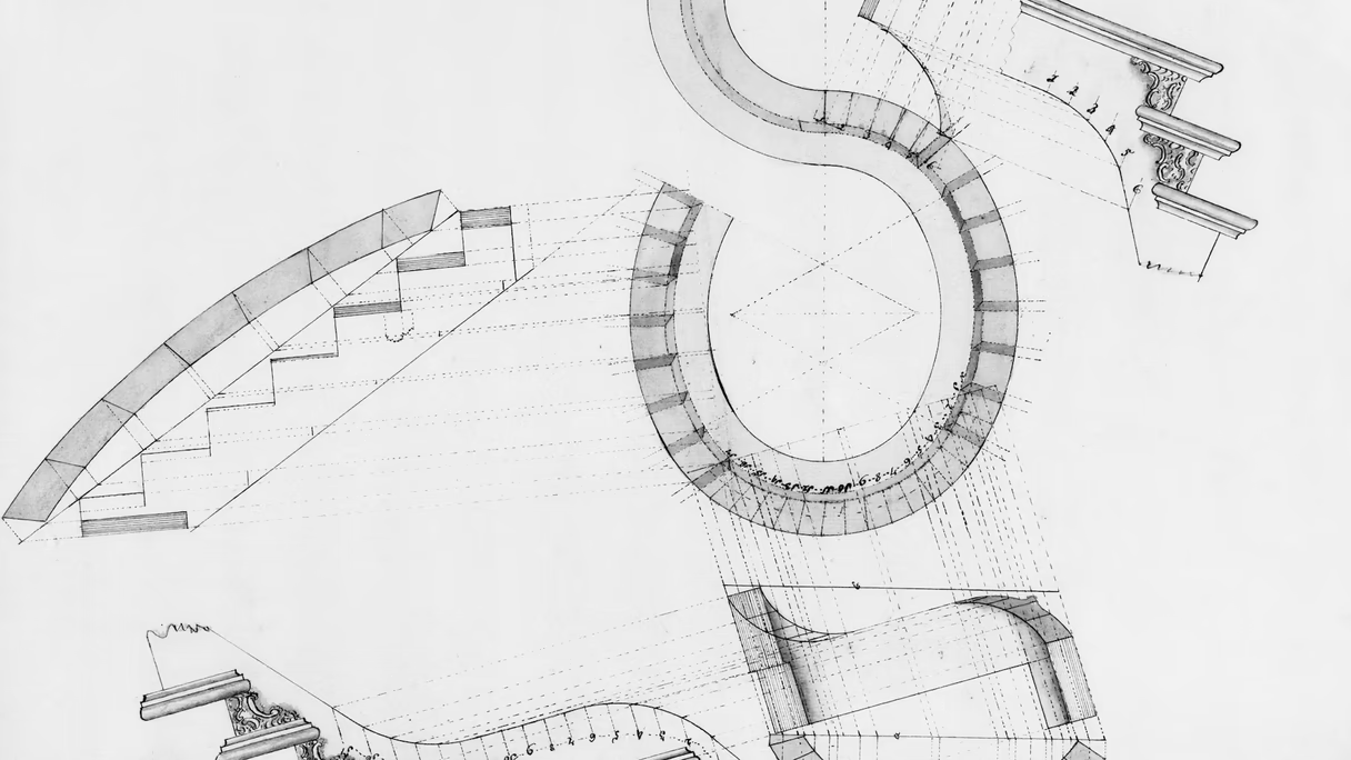
Details. A detail is a large-scale drawing of one connection or assembly, such as a window sill, a parapet or a stair nosing. It shows the layers and how they fit together, at a scale where those layers can be read. The HABS guidelines give door and window details at 1”=1’-0” and molding profiles at full scale in a typical set.
Schedules. A schedule is a table of repeated items: doors, windows, finishes, light fixtures. The drawings carry a tag, such as a door number, and the schedule gives the size, type and finish for that tag. Schedules keep the plans from filling up with notes.
Two other types appear in most sets. Large-scale views are enlarged plans, elevations or sections of crowded areas such as stairs, restrooms and core areas. 3D representations (isometrics, perspectives) are used to explain a condition that the flat views make hard to read.
Architectural drawing types at a glance
The table follows the sheet type designators of the Uniform Drawing System (UDS), part of the National CAD Standard. The “UDS sheet type” column is the first digit after the discipline designator and the hyphen, so a floor plan sheet is A-101 and an elevation sheet is A-201.
| Drawing type | What it shows | UDS sheet type |
|---|---|---|
| Site plan | The building on its lot and the features around it | 1, Plans (or in the civil or landscape set) |
| Floor plan | Walls, openings, stairs and rooms cut about 3 to 4 feet above the floor | 1, Plans |
| Reflected ceiling plan | Ceiling features drawn as if mirrored on the floor | 1, Plans |
| Roof plan | Roof outline, slopes, drainage, equipment | 1, Plans |
| Elevation | One exterior face or one interior wall, straight on | 2, Elevations and Profiles |
| Section | A vertical cut through the building | 3, Sections |
| Large-scale view | Enlarged plans, elevations or sections that are not details | 4, Large-Scale Views |
| Detail | One connection or assembly at a large scale | 5, Details |
| Schedule or diagram | Doors, windows, finishes in table form | 6, Schedules and Diagrams |
| General sheet | Symbol legends, notes | 0, General |
| 3D representation | Isometrics, perspectives, photographs | 9, 3D Representations |
The standard adds that using sheet type designators does not prevent combining different types of drawings on one sheet. On a small project, schedules often sit on a plan sheet and a section sits beside an enlarged plan.
How a set of architectural drawings is organized
In the United States, drawing sets are commonly organized to the National CAD Standard (NCS). Its Uniform Drawing System (UDS) module on drawing set organization defines a sheet identifier with three parts: a discipline designator, a sheet type designator and a sheet sequence number. The identifier A-201 reads as discipline A (Architectural), sheet type 2 (elevations), sequence 01. The hyphen is required as a placeholder when the designator has one letter.
The discipline designators in UDS include G (General), V (Survey/Mapping), C (Civil), L (Landscape), S (Structural), A (Architectural), I (Interiors), F (Fire Protection), P (Plumbing), M (Mechanical), E (Electrical) and T (Telecommunications). Within a discipline the sequence number starts at 01 and runs to 99, and sequence 00 is not permitted.
UDS also describes a convention for plans: it may be desirable to repeat the floor name within each discipline, so that A-102, M-102 and E-102 are the second floor plans of the architectural, mechanical and electrical sets. The standard warns that this becomes awkward when a building has basements, mezzanines or split levels.
Two terms are often confused here. Architectural drawings are the A sheets. Construction drawings are the whole set issued for construction, which includes the architectural sheets and the structural, mechanical, electrical, plumbing and other discipline sheets. So the difference between construction drawings and architectural drawings is scope: the architectural drawings are one discipline inside the construction drawings.
Scales
Scale depends on what the sheet has to show. The HABS guidelines, written for measured drawings of historic buildings, state that 1/4”=1’-0” is a useful scale for most building plans, elevations and sections, that very small buildings may need a larger scale, and that very large buildings may be drawn smaller, then shown in pieces at a larger scale. They also state that plans and elevations are always drawn at the same scale and that sections are typically drawn at the same scale, or one scale larger when the interior is detailed. Other offices and other project types use other scales, and the scale is written under each drawing’s title, usually with a graphic scale bar.
Design drawings, construction documents and as-builts
The same building has different drawings at different stages. The American Institute of Architects (AIA) describes the common phases of architectural services, and each phase produces its own drawings.
- Schematic design produces study drawings that show spatial relationships, scale and form for the owner to review. The AIA lists a site plan, floor plans, sections, an elevation and illustrative material as typical deliverables, with overall dimensions.
- Design development takes the schematic design one step further and lays out the mechanical, electrical, plumbing, structural and architectural details. Its drawings often specify materials and the location of windows and doors, and typically include floor plans, sections and elevations with full dimensions.
- Construction documents are the drawings, with specifications, that contain all pertinent information the contractor needs to price and build the project. They are what the building is permitted, bid and built from.
After construction, two more documents exist. The contractor’s marked-up set records the changes made on site, and the architect’s closeout set is compiled from those markups. Neither is a measurement of the finished building. The guide to as-built drawings vs record drawings explains what each is and who prepares it. The AIA notes that the deliverables it lists are examples and that the contract may spell out what is to be delivered, so a project’s scope is set in its agreement, not by this list.
Everything above describes drawings made before or during construction. A building that has stood for years has usually changed. Tenants move walls, owners add equipment, and repairs alter roofs. A drawing of the building as it exists today has to be measured.
How drawings of an existing building are produced from a laser scan
When no reliable drawing of an existing building exists, the drawings are made from measurements. Today the measurement is often a 3D laser scan. A scanner records the surfaces it can see from many positions, and the scans are registered into one point cloud, a set of measured points in 3D space.
The drafter then traces the point cloud. A floor plan is a slice of the cloud at the plan cut height, traced as walls, openings and stairs. An elevation is the cloud viewed straight on from one side. A section is a slice through the cloud along any line, and the cut can be chosen after the survey wherever the scan has coverage. The result is the same set of sheet types listed above, drawn to the building as it stands, with an accuracy that is stated. USIBD’s Level of Accuracy framework is the usual way to state it in the United States.
A scan records what the scanner can see. Framing inside walls, buried utilities and the inside of closed ceilings are not in the point cloud, and the drawings mark them as not verified or draw them from other documents.
We deliver as-built drawings of existing buildings as floor plans, reflected ceiling plans, elevations, sections, roof plans and site plans in DWG and PDF, traced from a registered point cloud.
FAQ
What are architectural drawings?
Architectural drawings are scaled drawings that describe a building: plans, elevations, sections, details and schedules. They are used to design, permit, price and build it.
What are the types of architectural drawings?
The main types are the site plan, floor plan, reflected ceiling plan, roof plan, elevations, sections, details and schedules. In a US set organized to the Uniform Drawing System, they are numbered by sheet type: 1 for plans, 2 for elevations, 3 for sections, 4 for large-scale views, 5 for details and 6 for schedules and diagrams.
What is the difference between construction drawings and architectural drawings?
Construction drawings are the complete set issued for building, covering every discipline. Architectural drawings are the architect’s sheets inside that set, marked with the discipline letter A. The structural, mechanical, electrical and plumbing sheets are the other disciplines in the construction set.
What does A-101 mean on a drawing?
In the Uniform Drawing System, A is the Architectural discipline, 1 is the sheet type (plans), and 01 is the sequence number. A-101 is usually the first architectural floor plan sheet.
What scale are architectural drawings?
It depends on the sheet. The HABS guidelines call 1/4”=1’-0” a useful scale for most building plans, elevations and sections and give 1”=20’-0” and similar engineering scales for site plans. The scale is written in each drawing’s title.
How are architectural drawings made for an existing building?
They are measured, today often with a 3D laser scan, and then traced from the registered point cloud into plans, elevations and sections. The scope states the accuracy to which they are drawn.
Sources
- National CAD Standard, Uniform Drawing System Module 1: Drawing Set Organization: sheet identifier format, discipline designators, sheet type designators 0 to 9, combining types on one sheet, repeating floor names across disciplines.
- National Park Service, HABS Guidelines for Measured Drawings (2008): drawing scales, same scale for plans and elevations, sections, details and the typical sequence of sheets.
- AIA Best Practices, Defining the Architect’s Basic Services (BP 11.02.01, 2007): schematic design, design development and construction documents phases and their typical drawings.
- City Tech (CUNY) OpenLab, Lesson 3: Introduction to Architectural Drawings, Elevations: definitions of plan, section and elevation, and the plan cut height.
- USIBD, Level of Accuracy: the framework for stating the accuracy of drawings made from scans.