Roof Plan: What It Shows, How Slope Is Noted, and Who Uses It
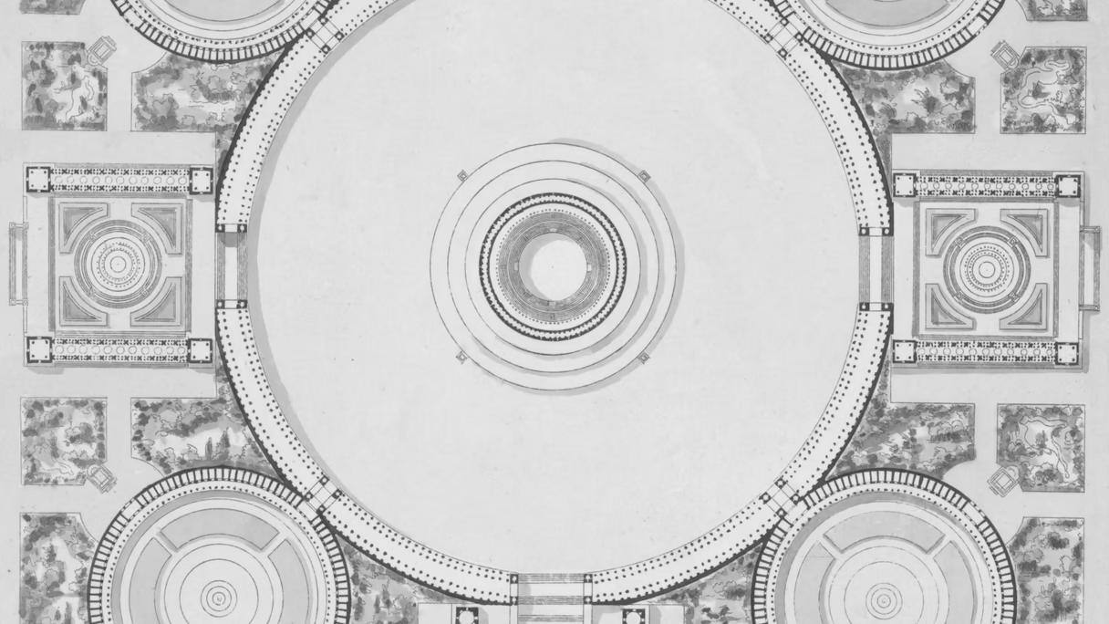
A roof plan is a scaled drawing of a roof seen from directly above. It shows the roof’s outline, its slopes, its drainage and everything that sits on it or passes through it. Architects use it to design a roof, roofers to price and install one, and engineers to place rooftop equipment. This guide explains what a roof plan contains, how slope is written on it, how it differs from a site plan and a reflected ceiling plan, and how one is produced for a building that already exists.
What is a roof plan
A roof plan is a top-down, scaled view of the roof. One drafting-software publisher defines it as “a scaled drawing that shows the shape, layout, and features of a roof from a top-down view” and says it can include slopes, ridges, valleys, drainage, vents and the placement of materials. A roofing trade study guide describes the same thing as an orthographic projection looking straight down on the building.
Unlike a floor plan, a roof plan has no cut plane through the building. Nothing is sectioned. The sheet shows the outermost surface only, so every line on it is either an edge of the roof, a change of slope, or an object standing on the roof.
What a roof plan shows
A complete roof plan covers these groups of information.
Outline and overhangs. The building edge below the roof is often shown dashed, and the roof edge is drawn solid. The distance between them is the overhang, eave or rake. The National Park Service’s HABS drawing guidelines note that overhang information may need to be captured separately so the roof edges can be located accurately, because buildings are measured to exterior wall corners.
Ridges, hips and valleys. On a pitched roof, a ridge is the high line where two slopes meet, a hip is a sloped line running from an exterior corner up to the ridge, and a valley is the sloped line where two slopes meet at an inside corner and water runs inward. These lines are what let a reader rebuild the roof’s shape from one view.
Slope. Each roof plane carries a slope note and, usually, an arrow pointing downhill. On a low-slope roof the arrows lead toward drains. How the value is written is covered in the next section.
Drainage. Roof drains, scuppers (openings through a parapet or wall), gutters and downspouts are located and tagged. A cricket (also called a saddle) is a small raised ridge built to divert water around the uphill side of a chimney, curb or large unit. On a low-slope roof it is usually formed from tapered insulation and drawn as a diamond or triangle with its own slope arrows.
Penetrations and equipment. Plumbing vents, exhaust fans, skylights, roof hatches, smoke vents, rooftop mechanical units and their curbs, antennas, solar arrays and lightning protection are placed and dimensioned. Curbs matter because every curb is an edge the roofing has to be flashed to and a dam that water has to be routed around.
Parapets, walkways and materials. Parapet walls, expansion joints, roof access, walkway pads and the roofing material (membrane type, shingles, standing seam) are noted. HABS drawings, for example, indicate the roofing material with a small vignette of its pattern.
Spot elevations are added where needed, typically at drains, parapets and equipment, so the roof’s high and low points can be read directly.
How slope is noted on a roof plan
Pitched roofs are noted as rise over run. Slope is written as the inches of vertical rise per 12 inches of horizontal run, so a roof that rises 6 inches over 12 inches of run is written 6:12. On the sheet this is often drawn as a small right triangle with the horizontal leg marked 12 and the vertical leg marked with the rise, or as a ratio next to the slope arrow.
Pitch is a related but different measure. The trade study guide defines pitch as the total rise compared with the full span of the building, so a pitch figure and a slope figure should not be swapped for each other.
Low-slope roofs are often noted in inches per foot or as a percent. The International Building Code sets a minimum design slope for most membrane roof systems at one-quarter unit vertical in 12 units horizontal, which the code calls a 2-percent slope. A note such as “1/4 in. per ft. min. slope to drains” on a flat commercial roof means exactly that. Steeper coverings have their own minimums. As summarized by NRCA’s Professional Roofing, the 2018 IBC sets 2:12 for asphalt shingles, 2 1/2:12 for clay and concrete tile, 3:12 for metal shingles, wood shingles and metal panels with nonsoldered seams without applied lap sealant, and 4:12 for slate and wood shakes. Manufacturers can ask for more, so the roof plan states the slope the specification requires.
Roof plan vs site plan vs reflected ceiling plan
The three are often confused because all of them look at the building from above or below. They answer different questions.
| Roof plan | Site plan | Reflected ceiling plan | |
|---|---|---|---|
| Viewpoint | Looking down at the roof | Looking down at the whole lot | The ceiling seen as a reflection from above, in the same orientation as the floor plan |
| Shows | Roof edges, slopes, drains, penetrations, equipment | Property lines, building footprint, drives, utilities, grading | Ceiling heights, grids, lights, diffusers, sprinklers |
| Scale | Building scale | Lot scale, smaller | Same as the floor plan |
| Main users | Roofers, structural and MEP engineers, solar designers | Civil engineers, planners, permit reviewers | Interior designers, MEP, ceiling contractors |
| Relation to the roof | The subject | The roof appears only as an outline or pattern | Shows the ceilings inside, not the roof |
In most construction sets the roof plan is its own sheet in the plan series. The HABS guidelines for historic documentation are a special case: they state that “the roof plans of buildings are shown in site plans,” and they also list a Roof Plan among the separate sheets of a measured drawing set. The reflected ceiling plan guide explains the ceiling sheet, and sections show how the roof structure meets the floors below.
Who uses a roof plan
- Architects use it to resolve the roof’s shape, drainage layout and the location of every penetration before the construction set is issued.
- Roofers and roofing consultants take quantities from it: area, perimeter, flashing length, number of curbs and drains, and the length of walkway.
- Mechanical, electrical and plumbing engineers place and dimension rooftop units, exhaust fans, condensers and drain lines. See MEP facility scanning for the equipment side.
- Solar designers need the usable roof area after setbacks, parapets, vents and shaded zones are subtracted.
- Structural engineers check the roof framing against equipment loads and ponding water.
- Insurers and appraisers use it to understand roof size, type and condition.
- Facility managers use it to track drains, equipment and past repairs.
What a roof plan is used for on an existing building
Reroofing. A reroof is priced from an accurate roof area, perimeter and a count of every curb, drain and penetration. In the replacement or re-cover of an existing low-slope roof, the 2018 IBC waives the 1/4:12 minimum slope and requires positive roof drainage instead, as NRCA’s Professional Roofing notes; the code defines positive drainage as drainage of the roof within 48 hours of precipitation. The existing slopes and drain locations on the plan are what a designer checks that against, and the edition the jurisdiction adopted governs.
Rooftop equipment replacement. A new unit rarely matches the old one exactly. The plan shows the existing curb, its position relative to parapets, other units and drains, and the clear space around it.
Solar layout. Panels are laid out on the plan after fire access paths, setbacks and obstructions are subtracted.
Drainage checks. A designer can compare slope arrows, spot elevations and drain locations to find areas where water cannot reach a drain. The code requires secondary (emergency overflow) drains or scuppers where the roof perimeter extends above the roof so that water could be trapped if the primary drains back up, and scuppers may not have an opening dimension smaller than 4 inches, as quoted in the 2015 edition. Local jurisdictions adopt their own editions, so the adopted code governs. NRCA, the roofing contractors’ association, recommends that membrane, liquid-applied and spray foam roof systems be sloped to provide positive drainage, and notes that some ponding along cricket and saddle valleys should be anticipated.
How a roof plan is made for an existing building
Old roof plans are often missing, and when they exist they show the design, not what was built after later repairs, added units and re-slopes. For an existing building, the roof plan is drawn from measurements.
The roof can be measured with a tape and a level, which records only the points someone chose to measure, or with a 3D laser scanner set up at several positions on the roof, with aerial capture where a large roof needs it. Each scan records the parapets, curbs, units, drains and the roof surface itself as a dense set of measured points. The scans are registered into one point cloud, and the plan is traced from the cloud: edges, parapets, curbs, equipment footprints and drain locations as measured, with spot elevations read from the cloud. Because the cloud is three dimensional, slopes and low spots can be checked directly, to the accuracy stated for the survey; a 2 percent slope is a small height change over a short distance, so the scope should say how slope will be checked. What the scan records on a roof, and what it cannot, is covered in the guide to laser scanning for roof inspections.
We deliver roof plans in DWG and PDF as part of as-built drawings, traced from a registered point cloud and drawn together with the floor plans, elevations and sections. If the roof is part of a larger renovation, existing conditions documentation shows how the roof sheet fits the rest of the set.
A scan sees surfaces. Membrane thickness, insulation layers, deck type and any leak behind the surface are not visible in it and come from a core sample, an infrared survey or the original documents.
FAQ
What is a roof plan in architecture?
A scaled drawing of the roof viewed from directly above. It shows the roof’s outline, slopes, drainage, penetrations and equipment.
What is the difference between a roof plan and a site plan?
A roof plan shows the roof in detail: slopes, drains, vents and units. A site plan shows the whole property, and the roof appears on it only as an outline or a material pattern.
How is roof slope shown on a roof plan?
Pitched roofs are noted as inches of rise per 12 inches of run, such as 4:12, often with a slope arrow pointing downhill. Low-slope roofs are noted in inches per foot or as a percent, and the IBC minimum for most membrane systems is 1/4 inch per foot, about 2 percent.
What is the difference between a roof plan and a reflected ceiling plan?
A roof plan looks down at the roof from outside. A reflected ceiling plan looks up at the ceiling from inside and shows lights, grids and diffusers.
What is a cricket on a roof plan?
A small raised ridge, also called a saddle, that diverts water around the uphill side of a chimney, curb or large unit toward a drain. On a low-slope roof it is usually drawn as a diamond or triangle with slope arrows.
Can a roof plan be made from a laser scan?
Yes. A scanner set up on the roof records edges, parapets, curbs, units and drains as measured points, and the plan is traced from the registered cloud.
Sources
- Vectorworks, What is a roof plan: definition, contents of a roof plan, slope arrows and notations.
- National Park Service, HABS Guidelines: Recording Historic Structures and Sites with HABS Measured Drawings: roof overhangs, roof plans shown in site plans, roofing material vignettes, Roof Plan as a separate sheet.
- IIBEC, Secondary drainage and ponding requirements, IBC and IEBC: quoted IBC text on secondary drains, scupper size, minimum slope and the positive drainage definition.
- Professional Roofing (NRCA), Roof slope guidelines: NRCA recommendation of positive drainage, the IBC 2018 minimum slopes by covering, the reroofing waiver, and ponding along cricket valleys.
- Open Exam Prep, Architectural Roof Plans, Symbols, Dimensions and Pitch Calculations: slope as rise per 12 inches of run, pitch versus slope, scale, line conventions.