Section Drawing in Architecture: Types, Symbols and Uses
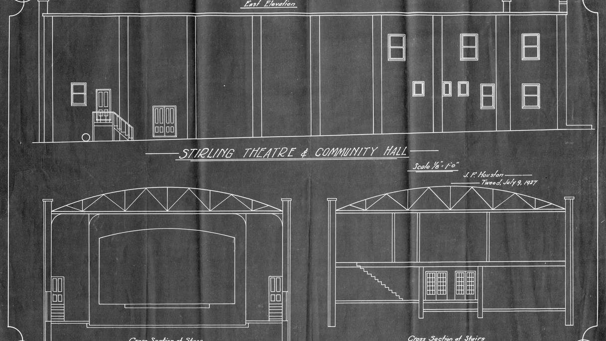
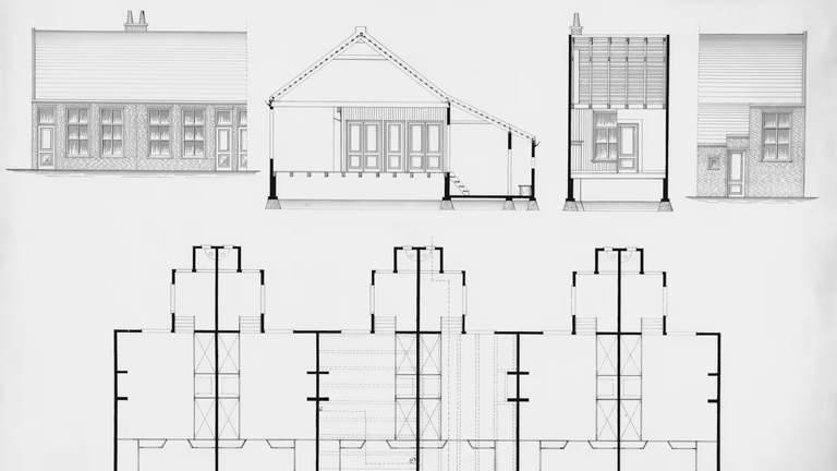
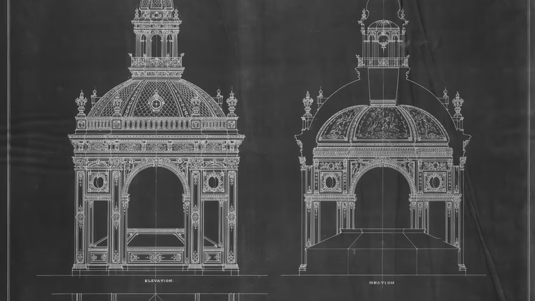
A section drawing is a view of a building as if cut by a vertical plane, showing the cut face and what lies beyond it. The part in front of the cut is removed, and the viewer looks in one direction. The cut elements (walls, floors, roof, stairs) are drawn heavier than the rest, so the structure and the spaces between the floors can be read at a glance. This guide covers what a section is, how the cut is marked on the plan, the four types, what a building section shows, how a section differs from a plan and an elevation, and how sections of an existing building are drawn from a laser scan.
What is a section drawing in architecture
An architectural section is an orthographic drawing made by imagining a vertical plane through the building and looking at the result. Architizer’s introduction to the subject describes a section as “a cut through the body of a building, perpendicular to the horizon line,” and a section drawing as one that “shows a vertical cut transecting, typically along a primary axis, an object or building.” The Designing Buildings wiki puts it as a view of a structure “as though it had been sliced in half or cut along another imaginary plane.”
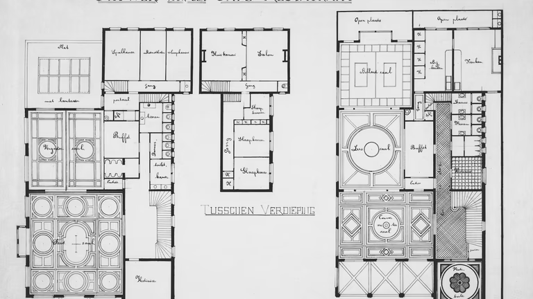
A plan is also a cut, but a horizontal one. Architizer notes that a plan cut passes mainly through walls, while a section can pass through walls and floors both.
Cut elements are drawn with the heaviest lines, and elements seen beyond the cut with lighter lines. Walls, floors and roofs can also be filled with a solid tone (poché), hatching or a material pattern so the cut stands out. This is a convention, and standards differ. The National Park Service rules for measured drawings of historic buildings, for example, give material cut lines in plan and section a 0.5 mm line on drawings plotted at 1/4 inch = 1 foot, and, unusually for US practice, state that “no poché is shown in walls and floors cut in section.”
How the section line works on a plan
A section is never drawn in isolation. Its location is marked on the plan (and on elevations) with a cutting plane line, usually a line of long and short dashes. Designing Buildings describes it as “a line of long and short dashes, called a section plane,” with letters at each end to name the section and an arrow showing the direction of view.
The marker carries three pieces of information:
- Where the cut is. The line runs across the plan at the position of the cut. It may jog to pass through a stair, a double-height space or an opening, and the jog is drawn on the line.
- Which way you look. The arrows point in the direction of view. Everything beyond the cut in that direction appears in the section.
- Where to find the drawing. The letter or number and the sheet reference tell the reader which sheet holds the section.
In US practice the sheets are organized by the Uniform Drawing System, part of the National CAD Standard. Its sheet type designator puts sections in group 3, described as “Sections (sectional views, wall sections),” so in the UDS format an architectural section sheet is numbered A-3xx. Plans are group 1, elevations group 2, large-scale views group 4 and details group 5.
The HABS guidelines add practical rules for placing the cut. Sections “should be cut where they provide the most information,” typically through unusual spatial situations such as double-height spaces, or through stairs to show the landing levels. They are cut through door and window openings wherever practical, and a section line “may not jog from one room to a room behind it, through a wall seen in elevation.”
Types of section drawings
Sections are named by the scale of the cut and what it is meant to show. Architizer lists four: site sections, building sections, wall sections and detail sections.
| Type | What is cut | What it shows | Typical use |
|---|---|---|---|
| Site section | The building and the ground around it | Massing, grade changes, neighboring buildings, streets, retaining walls | Zoning and design review, drainage and grading, context |
| Building section | The whole building, often along a main axis | Floors, roof, stairs, ceiling heights, vertical relationships between levels | Design, permits, structural and MEP coordination |
| Wall section | One exterior or interior wall from foundation to roof | Floor and roof connections, construction layers, insulation, openings | Construction documents, energy and envelope work |
| Detail section | A small part, such as a sill, a parapet or a stair nosing | Materials and joints at a large scale | Fabrication and installation |
Architizer notes that wall and detail sections “foreground technical concerns,” while a site section emphasizes “a built form’s massing and its relationship with its environment.” Building sections carry the widest range of concerns at once.
What a building section shows
A building section is the drawing that explains the vertical organization of a building. It normally shows:
- Floor-to-floor heights and floor levels. The HABS guidelines call for floor levels to be dimensioned in sections rather than elevations, and for floor-to-floor heights to be measured along strings taken through stair openings.
- Slab and roof structure. The depth of each floor assembly, beams and girders where the cut passes through them, the roof slab or framing and its slope.
- Ceiling cavities. The space between the finished ceiling and the slab above, where ducts, pipes, cable trays and sprinkler mains run.
- Stairs, ramps, shafts and double-height spaces. The cut through a stair gives the landing levels and the headroom.
Sections are normally dimensioned with vertical strings of dimensions. The HABS guidelines draw sections at the same scale as the plans and elevations, or one scale larger when the interior is detailed, and require all sections in a set to use one scale.
Section vs elevation vs plan
The three drawing types are all orthographic views of the same building. They differ in the direction of the view and in whether the building is cut.
| Plan | Elevation | Section | |
|---|---|---|---|
| View direction | Looking down | Looking straight at one vertical surface, an exterior face or an interior wall | Looking horizontally at a cut face |
| Cut | Horizontal | None | Vertical |
| Shows | Layout of walls, rooms, openings | Facade, openings, roof line, outside heights | Floor and ceiling heights, structure, vertical relationships |
| Cannot show | Vertical relationships between levels | Anything behind the surface | What lies in front of the cut |
| NCS sheet group | 1 | 2 | 3 |
An elevation of an existing building records the face as it stands. A section records the inside of the same volume. The set is read together: the plan locates the cut, the section gives the heights, and the elevation ties both to the facade. The guide to what an as-built drawing set includes lists the sheets in a typical set.
How sections of an existing building are drawn from a laser scan
For a new building the section is drawn from the design. For an existing one it has to be measured, and that is where a scan differs from a tape and a laser distance meter. A hand survey measures only along the line the surveyor chose, so a section that was not measured on the day is usually missing later.
A registered point cloud records every surface the scanner could see, inside and out, as one 3D set of points. A section is taken by placing a clipping plane through the cloud and viewing the thin slice of points on either side of it. The plane can go anywhere: through the stair, through the plant room, through the one corner where a beam appears to drop. The slice is then traced into linework, with cut elements drawn heavy and beyond-cut elements light, as on any other section. A cut that was not planned during the survey can be taken from the same scan wherever the scan has coverage.
Three limits apply. The scanner records surfaces it can see, so what is above a closed ceiling, inside a wall or under a slab is not in the cloud, and the section marks it as assumed or taken from other documents. The accuracy of the drawing is the accuracy of the cloud plus the tracing, which is stated with the USIBD Level of Accuracy. And a section through a leaning or out-of-plumb wall is drawn from the points at the cut, so the line on the sheet follows the wall and does not assume it is straight.
We deliver sections together with floor plans, reflected ceiling plans and elevations as as-built drawings in DWG and PDF, traced from a registered point cloud. Where the ceiling cavity needs to be modeled in 3D, the work moves to a Revit model, covered in the guide to scan-to-BIM for ceilings and plenums.
What section drawings are used for
- Renovation design. New floor openings, a new stair, raised ceilings or a mezzanine are checked against the actual floor-to-floor height and the existing structure. The guide to existing conditions documentation for renovation covers how this fits the rest of the survey.
- Structural checks. The section shows slab depth, beam depth and the relationship of floors, columns and roof. For work on structure see laser scanning for structural renovations.
- MEP coordination. The ceiling cavity is the tightest space in most commercial buildings. A section through the cavity shows how much depth is available for new ducts and pipes, below the structure and above the finished ceiling.
- Permits and approvals. Sections show building height, ceiling heights and stairs. Whether a jurisdiction asks for them with a permit set depends on the jurisdiction and the project type.
- Historic and heritage documentation. Measured drawings of historic buildings, such as those made to the HABS standard, include sections as a standard part of the set.
FAQ
What is a section drawing in architecture?
A section drawing shows a building cut by a vertical plane and viewed in one direction. It reveals floor-to-floor heights, slab and roof structure, stairs and the make-up of walls, which plans and elevations do not show.
What does the section line on a plan mean?
It marks where the vertical cut passes through the building. Letters at its ends name the section, and arrows show the direction of view.
What is the difference between a section and an elevation?
An elevation looks straight at one vertical surface, exterior or interior, and has no cut. A section looks at a cut face and shows the inside, including heights and structure.
What is the difference between a building section and a wall section?
A building section cuts the whole building, typically at a small scale, to show the floors, roof and stairs. A wall section cuts one wall from foundation to roof at a larger scale to show its layers and connections.
What is a site section?
A site section extends the cut beyond the building to include the ground, adjacent buildings and streets. It is used to show massing, grade changes and the building’s relationship to its surroundings.
Can a section be drawn from a laser scan?
Yes. A clipping plane is placed through the registered point cloud at any position, and the slice is traced into a section drawing. Cuts can be added after the survey, but areas the scanner could not see are not in the cloud.
Sources
- Architizer, Architecture 101: What Is a Section Drawing?: definition, section vs plan, the four section types and their purposes.
- Designing Buildings, Section drawing: definition, the section plane line with letters and arrows, cut elements marked with heavier lines or fills.
- National Park Service, HABS Guidelines: Recording Historic Structures and Sites with HABS Measured Drawings: where to cut sections, measuring floor-to-floor heights, line weight for cut lines, section scale, floor levels dimensioned in sections.
- National CAD Standard, Uniform Drawing System Module 1: Drawing Set Organization: sheet type designators (1 plans, 2 elevations, 3 sections).
- USIBD Level of Accuracy Specification: how the accuracy of drawings made from scan data is stated.